Speaking of push button switches, I firmly believe that many people are not unfamiliar with them, but if you really want to tell you why it is the key point, and accurately respond to the principle of push button switches, or make many people confused. Today, let us talk about the principle of push button switches and the wiring method of push button switches.
Principle of push button switch.
Push button switch refers to a power switch that uses buttons to promote the transmission mechanism, connect and disconnect moving contacts and static contacts, and complete power circuit exchange. The push button switch is a very common cam controller household appliance with a simple structure but very common use. In the automatic control circuit of electrical equipment, it is used to operate AC contactors, solenoid valves, electromagnetic induction starters, etc.
The push button switch can perform basic operations such as run, stop, forward and reverse, speed adjustment, self-locking interlocking, etc. Generally speaking, the power switch of each button has two contact points. Each contact point consists of a switching contact and a normally closed contact. When the button is pressed, the two contact points are positioned at the same time, often closing the contact and opening and closing the contact point.
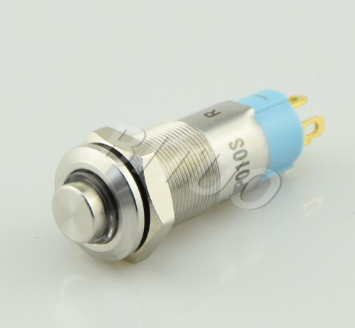
plug-in-quick plug button switch
In order to better mark the effect of each button and prevent operation errors, button caps are usually made in different colors to show different colors, including red, green, black, yellow, blue, white, etc. For example, bright red represents the kill button, green represents the start button, etc. The product manual describes in detail the basic parameters, form, mounting hole specifications, total number of circuit breakers, and current capacity of the circuit breaker of the push button switch.
How to wire a push button switch
The processing power of DC power supply is aggressive and low. The fundamental reason is that the DC power supply does not have a zero point (zero current junction point) like communication. Once the arc is difficult to clear, the arc time will be longer. Moreover, the direction of the current will not change, so the joint transfer will occur, and the joint will not break due to unevenness, which is likely to lead to operational errors.
There is a large distance between some types of constant current and surge current. It needs to be applied to the allowed surge current value category. The greater the surge current of cable digital TV, the greater the use and transfer of connectors. The welding and transfer of connectors will cause power switch failure.
In the case of electrical induction, it is easy to cause induced voltage in the opposite direction. The higher the operating voltage, the higher the efficiency, the greater the energy, and the loss and transfer of the joints also expand. Therefore, it is necessary to determine the standard of the rating and indicate the operating volume in the rating, but this is far from enough. In unique load circuits such as operating voltage, current waveform, load type, etc. when connecting and disconnecting, specific mechanical equipment testing and determination must be performed. Fine working voltage and current situations require the use of fine load products. When using general-purpose silver connectors, it is likely that touch stability will be reduced.